Making A Mechanical Iris
This post will use the building of a prototype of a Mechanical Iris to walk you through the steps involved in prepping data, material, etc. needed to use the laser cutter to make some parts for our nifty gadget.
Inspiration for this project came from Chris Schaie over on the ShopBot forum. Chris developed and shared a very cool mechanical iris he was incorporating into a Steampunk/Captain Nemo style door.
I’ll be incorporating the iris window in the door of my children’s playroom.
For background and some great discussion on the design and his build, the original thread can be found here:
talkshopbot.com/forum/showthread.php?t=795
File Prep
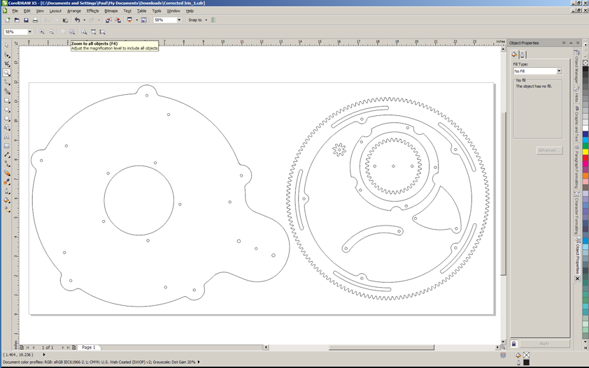
The first step was downloading the DXF design file from the above thread and opening it in CorelDraw.
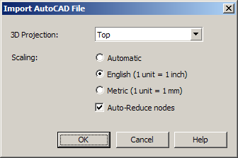
When you open a DXF in CorelDRAW you are presented with the following dialog box:
The DXF format is 3D and CorelDRAW is 2D so we need to tell it how to look at the object. Trial and error is the easiest way to determine the projection. I usually find that Top or Left is what I’m looking for.
We also need to indicate the scale of the illustration. I typically select English and then scale as needed once in CorelDRAW. Depending on the source of the DXF there may be a lot of extra detail or line segments that are not needed. More information on these settings can be found in the CorelDRAW documentation.
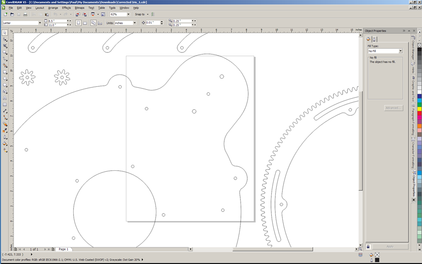
After the import we have the various shapes at actual size on an 8.5? x 11? page.
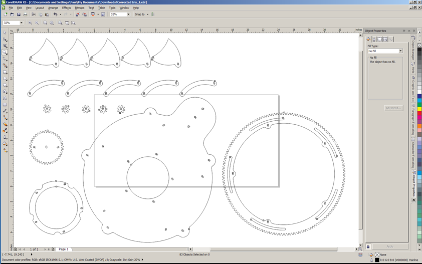
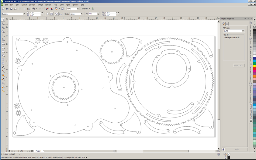
Since I want to get the maximum size out of my piece of material I first change the page size to the max size the cutter can accommodate 24? x 12? and zoom out to see all the parts.
I then group the elements of each part and move everything but the largest part off the page to give me more room to work. My personal preference is to also delete any duplicates, I’ll copy and paste as I nest the objects on the page.
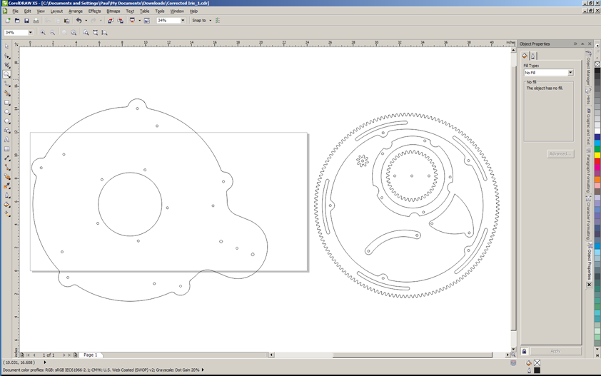
First step of nesting is to orient the part to get the max size for my material(12? high) and then scaling all of the parts by the same amount.
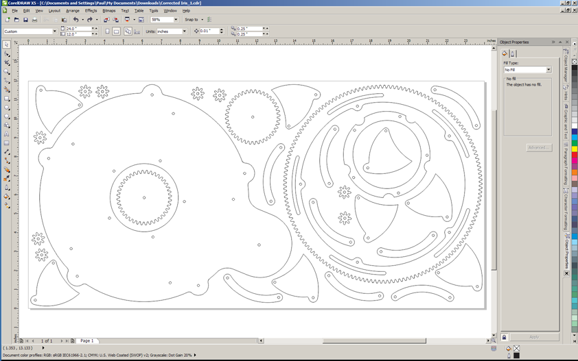
After scaling, begin to position the parts. I like to stay about 0.125? from the edge just as a safety margin. Remember to duplicate the parts you eliminated earlier.
Since I have lots of extra room, and since plywood is an irregular, natural product and because I’ve been known to make mistakes… I like to add sever extra parts of pieces that look like I may need to tweak or modify. I also removed a few extra fastener holes on the hand crank and the area on the base plate where it goes.
If you haven’t done it by now – save your file in CDR format – just in case…
Cutting Parts
Now… we cut!
No, not yet…
First we need to determine what settings to use for the laser and do test cuts to get everything dialed in. To determine the machine settings I first check the reference table in the manual to get a good starting point. The table in the manual for a 60W laser lists Speed 20, Power 100 and frequency 500 for 0.25? wood. This is a good starting point for a test. Remember that due to the glue used in manufacturing plywood it requires more energy than a solid board of the same thickness.
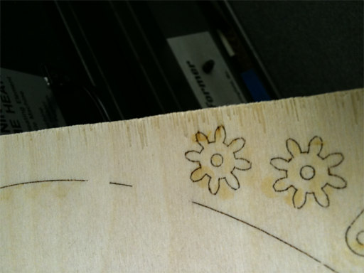
Also, unlike the ShopBot or other CNC tools, CorelDraw doesn’t have tool diameter(kerf) compensation. The laser cuts directly on the line. This means I need to take into account the kerf of the cut on my parts. If I use my calipers I can measure that 1? circle I cut to determine speed/power/freq and see what size it ended up being .
The diameter was 0.992?, 8 thousands of an inch less that the size of the object in CorelDRAW. For those more comfortable with fractional inch measurements 0.008? is just a hair more that 1/128? or about 1/2 of a 1/64? . Remember that since the laser cuts “on the line” 1/2 of the kerf (0.004?) is on the waste side of the line and 1/2 is on the part side of the line. Not huge by any means but depending on your project you will need to take this into consideration.
I’m not going to worry about my slightly smaller parts except for the fastener holes. Since this is a geared mechanical movement and the fasteners will be acting as axles for many parts I don’t want a lot of slop.
In the drawing, after scaling, the fastener holes are 0.122? and the slots are 0.187?. Adding the 0.008? kerf makes the holes 0.130? and the slots 0.187? wide. 0.13? is perfect for a #5 machine screw – except that #5 is an odd ball size and I don’t want to spend more in hardware that the rest of the project combined. Checking my parts bins I have a bunch of #6 screws that I’d like to use. 0.15? will give me a good fit on the #6 screws. Subtracting the kerf makes my measurement for the circles in CorelDRAW 0.142? – so going slow and making sure I don’t miss any I select each circle in turn and resize it to my new size.
Now the slots in the gear – at 0.187? that will give me 0.195? with the kerf. I’d like to use a standard nylon bushing since this slot acts as a guide for the rotating ring gear. Lowes had 2 1? x 3/16? with a 0.177? hole for $0.55. Sold!
I’d like the fit a hair closer – about 4 thousandths oversize. So working back to the size I need in CorelDRAW I end up offsetting the slots(to the inside) by 0.002? for a final dimension of 0.183?. Due to rounding errors and CorelDRAW’s decimal point limitations the slots ended up being 0.003? larger than the OD of the bushing. Close enough!
NOW WE CUT ! ! !
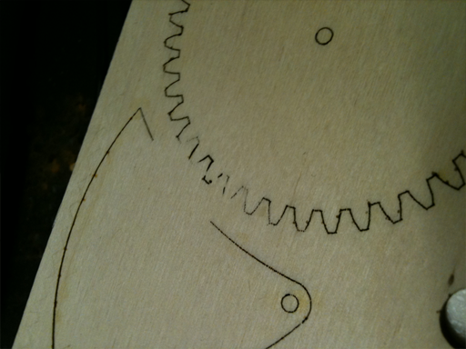
After cutting I found that some parts did not cut completely through. This is most likely due to irregularities in the plywood. The solution was to slow the speed to 15% and cut again. That left just a handful of small places where I needed an x-acto to trim from the back side to finish the cut.
Cut time at 15% Speed was just over 15 minutes.
Hand Work
So despite all the math and test cuts the holes for the fasteners were a bit undersized. The screws would go in with a screwdriver but were too small for any part that needed to spin freely. After thinking a minute I decided this was a good thing – the ‘fixed’ screws would be more stable and I could do some trial and error to find a good diameter for the free spinning parts.
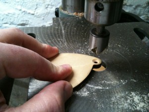
Pulling out my calipers, a #6 screw and my drill index I made some test holes and determined that a #29 drill worked well. I drilled out the connector arms, drive gear, the 5 small gears and the
Next up was drilling the countersink for the ‘fixed’ screws. Most flat head fasteners have an included angle of 82° degrees but not all – 90° & 100° are also used. It doesn’t matter much for this project, just make sure the screws and countersink match. Back to the drill press with some scrap and a countersink for some trial and error to get my depth stop set. Start with a scrap piece with a tight clearance hole for the #6 screw. Adjust the table to an inch or so below the countersink and bring the bit down until it just touches the work and set the collar. Release the quill and adjust the collar depth to something that ‘feels’ about right. I started with 0.125?
Drill a test in the scrap and see how it fits. I fiddled with the depth stop until I had the screw head recessed about 1/32?.
Next I drilled all the holes that needed a countersink. Pay attention to which side of the part you are drilling! This is where I was glad I had an extra iris leaf – or two.
Finishing
It’s easier to finish the pieces before you assemble. First step is sanding – looking back I should have sanded the 24? x 12? panel before cutting the parts – that would have just left the edges to clean up.
I’ve also seen several suggestions to finish the wood prior to cutting – this makes the scorch marks on the top and bottom surfaces easier to remove. This will depend on your what your finish is – some choices may not be laser friendly(paint?). Dark stain and clear coat appear to work well and will minimize the contrast with the cut edges – I’d go with water based finishes as they are less likely to give off nasty fumes when cut.
For my prototype I went with a simple wax finish.
Easy & quick to apply and reduces friction between the parts that slide against each other. An old toothbrush is helpful for working wax into the gear teeth.
Assembly
Pretty straight forward(but I forgot to take pics) – using a manual screw driver I first threaded the screws into the ‘fixed’ locations – this included the base plate and the arm attach point on the iris leaves.
Starting with the base right side up I first add the bushings for the ring gear
Then the first layer of floating elements – the ring gear and the iris leaves.
Next add the inner iris support ring and the idler and drive gears. After a test run I found the idler gears to be more trouble than they’re worth and, like Chris, removed them.
Add the connector arms
Finally the acorn nuts.
After everything is assembled I give the drive gear a turn…
Final Tweaks
The last step on the Mark I prototype is to trim any screw that are too long and reassemble with a dot of thread locking glue to prevent things from rattling apart.
Materials
6mm baltic birch plywood 24? x 12?
(26) 6-32 stainless steel machine screws of various lengths with acorn nuts
Locktite
Tools
Epilog Mini 24 60W laser cutter
Vector Cutting with Air Assist
Settings: 100% Power, 20% Speed, 600 Hz pulse freq.
Timing
File prep time on the computer was about an hour.
Total machine time with test cuts and tweaks was another hour.
Assembly & Finishing – 3 hours – lots of sanding and waxing.
What’s Next?
This build got me thinking about lots of different variations – currently I’m in the processing of adding a knob to the drive gear for easier manual operation. Maybe a RFID key or a rotary encoder/LCD based combination lock?
UPDATE:
I did design an alternate base plate to accept a micro-controller driven servo to the drive gear.
For this version I used an Arduino Uno with an Adafruit(Ladyada) Motor Shield
Iris + Arduino + Stepper from Lepton on Vimeo.
Onions & Taters
Quick and dirty project for the kitchen.
We have been looking for a better way to store produce in the kitchen and try and make use of some dead space behind the door.
My father-in-law ‘found’ this Ikea CD tower and asked if it would work. A few quick measurements and it seemed like it might. F.I.L. brought it over and we cut out a notch for the baseboard and added an angle bracket to the top to hold it securely.
Diane found some clear polycarbonate trays that fit perfectly and would work for most of the hand fruit.
The problem was storage of onions and potatoes since we buy those 5lb at a time. The trays didn’t hold enough and things wound up on the floor.
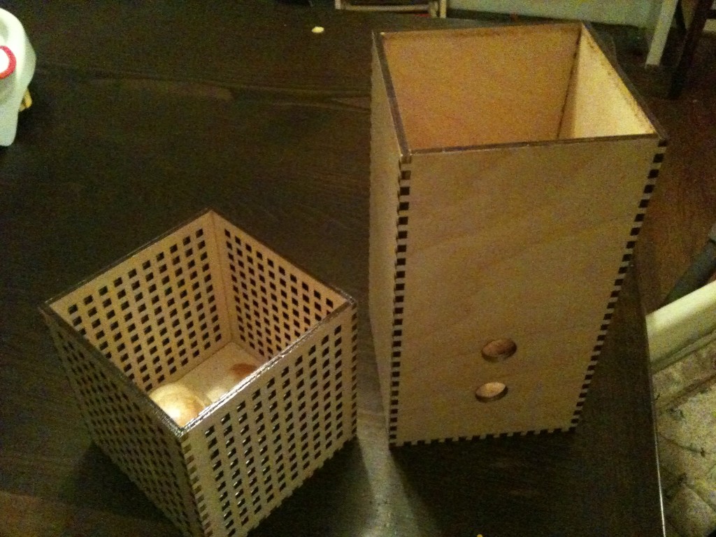
I had been playing with finger joints on the laser cutter and though this might be a good test project. I had a scrap of 6mm Baltic birch plywood and after a few test cuts I was ready to go. The laser cut the boxes in less than 20 minutes and after some glue, sanding and several coats of poly…
The birch is close enough in color and grain to the Beech that unless you really look everything matches.
Next up – banana hook!
New Instructables
I finally managed to document two recent projects and get them on Instructibles.com
Both are entered in current contests – have a look and vote for them! Voting is only through Thursday 7/7 – you can vote for more than one.
Vote early and often – a lot of good stuff!
